
At a glance
- Role
- Product design student
- Team
- Individual project
- Tools
- Fusion
- Timeline
- Third year of my BSc Product Design (2020–2021)
- Status
- College project, BSc Product Design at TU Dublin
What it shows
- Designing for injection moulding
- Stress testing to a 3.00 factor of safety
- Ribbing and snap fits
- Draft angles, ejection pins and split lines
Highlights
- 3.00 factor of safety, kept through numerous stress tests
- 1 mould needed, because the rack is symmetrical
Discover
A project that I worked on recently was to design a pannier rack that was made from plastic. This was one of the more difficult projects, as it had to be ready for manufacture. Therefore it meant exploring many new routes that I had not done before.
How it came together
5 steps · 1 rework · 1 milestone
- Step
- Rework: went back and changed something
- Milestone
1Define
The brief
A pannier rack made from plastic, ready for manufacture.
2Design
Minimising material
Ribbing, and numerous stress tests in Fusion, keeping within a 3.00 factor of safety.
Reworked later in05
A symmetrical rack
So only one mould would need to be used.
Snap fits for injection moulding
Snap fits that work with both the design of the product and the injection moulding expectations.
The CAD restarted, multiple times
Back to 02: Minimising material
Why: Designing for manufacture changed the way I look at projects: I ended up having to restart my CAD multiple times.
3Deliver
Drafts, ejection pins and split lines
The drafts of each face made compatible with a mould.
4Outcome
Final renders
Define
Being ready for manufacture meant the rack had to:
- use as little material as possible without losing strength
- need only one mould
- snap together in a way that suits injection moulding
- have faces that release from a mould, with room for ejection pins and split lines
Design
I had to find ways to minimise the material use in the design while ensuring that its strength was not affected. This meant the use of ribbing, and numerous stress tests through Fusion to ensure that the product remained within a 3.00 factor of safety.
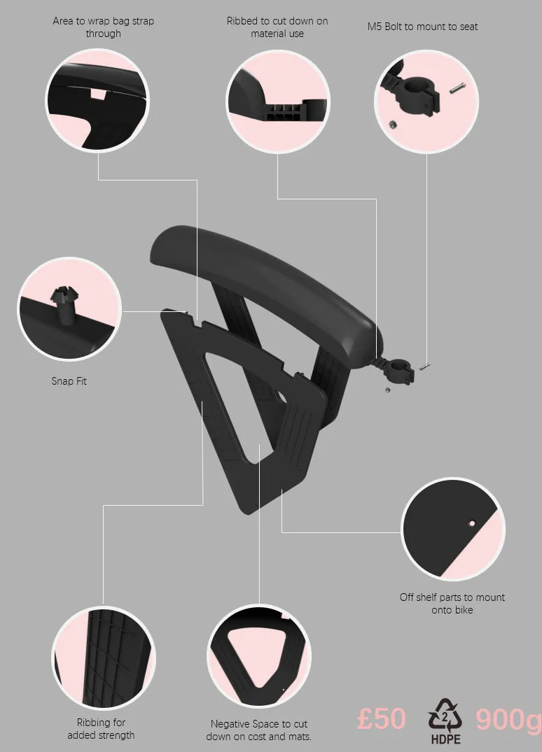
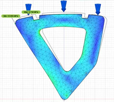
In order to ensure a more realistic design, I had to find a way to make the rack symmetrical, so that only one mould would need to be used.
I had to design snap fits that worked in conjunction with the design of the product and the injection moulding expectations. This entire process changed the way that I look at projects, as I ended up having to restart my CAD multiple times.
Deliver
Finally, I had to ensure that the drafts of each face were compatible with a mould, along with the inclusion of potential ejection pins and split lines.
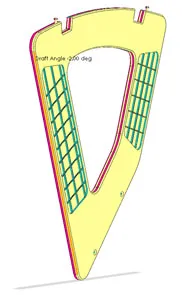
- 3.00Factor of safety the rack stayed within through numerous stress tests
- 1Mould needed, because the rack was made symmetrical
Outcome
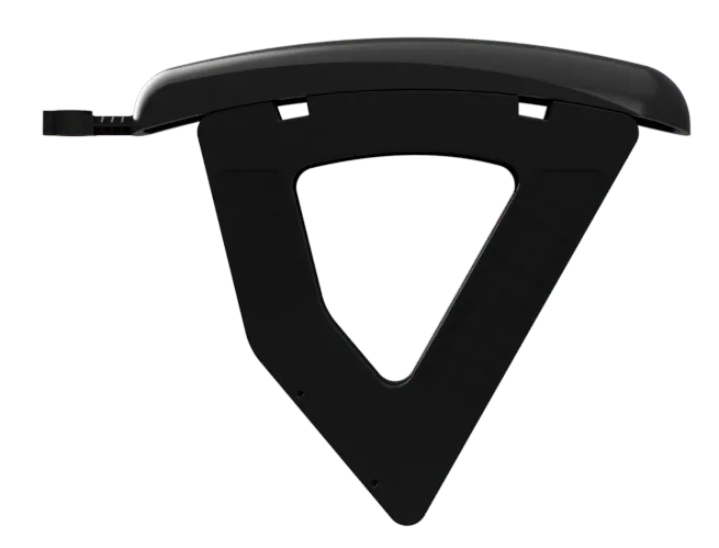
Renders of the final design.
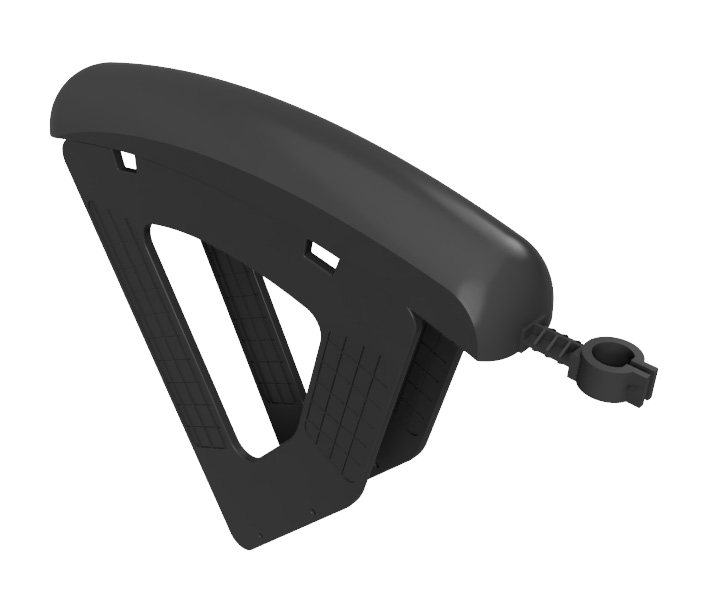
Three-quarter view. 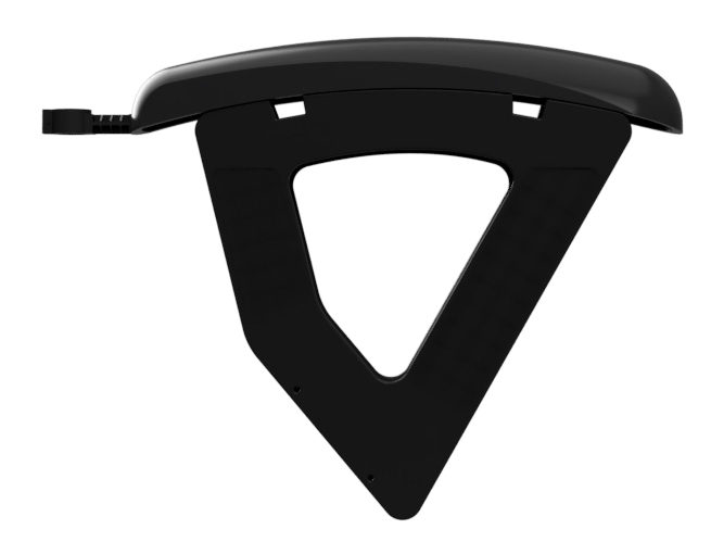
Side view. 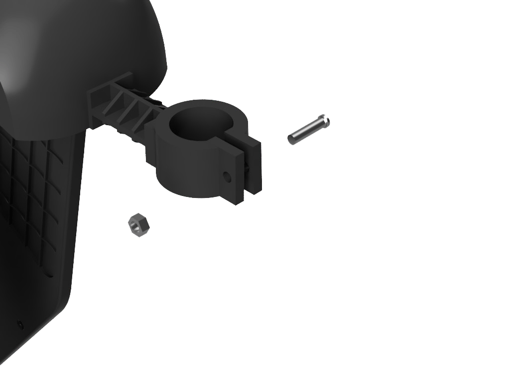
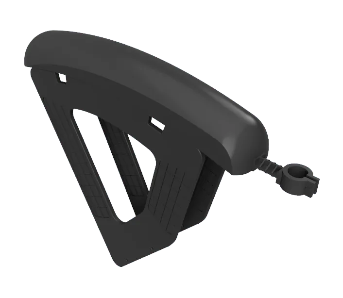
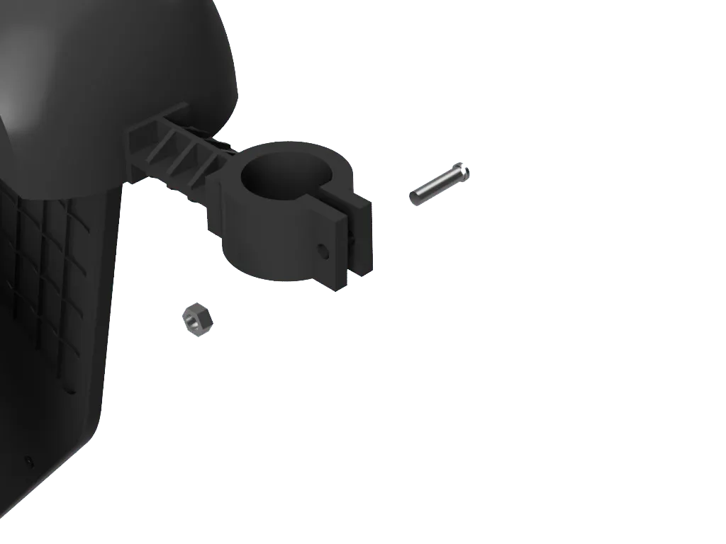
The clamp that mounts it to the seat post.
What’s next?
- A physical prototype. Testing the snap fits, how the rack mounts to a real seat post and how it carries a packed bag would check the CAD and the stress tests in the real world.
- A manufacturer’s review. A toolmaker could check the mould design (the drafts, ejection pins and split lines) and confirm the cost before anything is made.